

| 1. Selection of vacuum suction cups | ||||||
| Weight of the suspended item | W= | 20 | Kg | |||
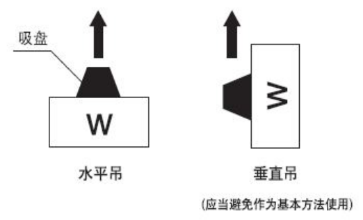
| Safety factor | t= | 4 | Horizontal lifting t≥4 Vertical lifting t≥8 | |||
| Vacuum safety factor | 60% | 63%-95% of the maximum vacuum | ||||
| Maximum vacuum | Pv= | 0.088 | Mpa | Maximum vacuum of standard vacuum generators | ||
| Vacuum inside the suction cup | p= | 0.0528 | Mpa | |||
| Number of suction cups | n= | 6 | ||||
| Calculated diameter of the suction cup | D1= | 56.13 | mm | |||
| ★: Required suction cup diameter D≥D1 | ||||||
| The vacuum inside the suction cup p should be selected within 63%-95% of the maximum vacuum Pv of the vacuum generator (or vacuum pump) to enhance the suction capability without causing excessive response time. | ||||||
| Note: By sequentially inputting parameters W, t, p, n, Pv, etc., the theoretical diameter of the suction cup can be automatically calculated. | ||||||
| 2. Calculation of required vacuum | ||||||
| Suction cup diameter | D= | 60 | mm | Required suction cup diameter D≥D1 | ||
| Required vacuum for lifting | P= | 0.0462 | Mpa | |||
| 3. Calculation of the maximum suction flow rate of the vacuum generator | ||||||
| Suction cup adsorption volume | V= | 0.1 | L | Volume from the vacuum generator or switching valve to the suction cup | ||
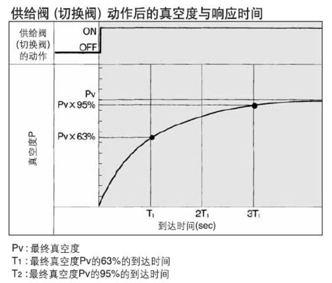
| Arrival time | T1 | 1 | s | Time to reach 63% of the final vacuum Pv | ||
| Coefficient | Cq= | 0.5 | Cq=1/2 to 1/3, generally taken as 1/2, if resistance is high, can take 1/3 | |||
| Average suction amount of the vacuum generator | qv1= | 6 | L/min | |||
| Maximum suction flow rate of the vacuum generator | qve1= | 12 | L/min | |||
| Note: Select the model of the vacuum generator based on the calculation results. | ||||||
| 4. Verification of response time | ||||||
| Maximum suction flow rate of the vacuum generator | qve= | 24 | L/min | Determined by model | ||
| Response time | T1= | 0.500 | s | Time to reach 63% of the final vacuum Pv | ||
| Percentage of reaching maximum vacuum | 53% | |||||
| Actual response time | T= | s | Time to reach the required vacuum P, the relationship between T and T1 can be calculated from the table. | |||
| ★: Required qve≥qve1 | ||||||
| 5. Verification of pipe diameter | ||||||
| Diameter of connecting pipe | d= | 4 | mm | Determined by model | ||
| Length of pipe | l= | 1 | m | |||
| Effective cross-sectional area | S= | 6.71 | mm2 | Should not be less than 4 times the nozzle of the vacuum generator | ||
| Average suction flow rate of the piping | qv2= | 37.26 | L/min | Must be greater than qv1 | ||
| In the case of using a vacuum pump system: | ||||||
| 6. Calculation of effective cross-sectional area of the vacuum switching valve | ||||||
| Effective cross-sectional area | Sc= | 1.08 | mm2 | |||